Schedule 40
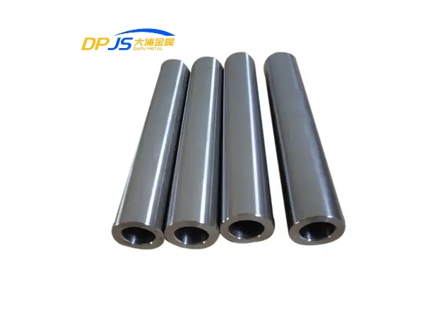
Steel Pipe
The essential industrial standard for high-efficiency fluid transport. At SS Alloy Steel, we provide premium Schedule 40 pipes in Carbon and Stainless Steel, engineered for durability under pressure.
Sch 40 Pipe Dimensions & Weights
Precise engineering requires accurate data. Our Schedule 40 (Standard Weight) dimensions are manufactured to ASME B36.10M standards, ensuring seamless compatibility with industrial fittings and valves.
| NPS (Inches) | DN (mm) | Outside Diameter (OD) | Wall Thickness (Sch 40) | Weight (lb/ft) | Weight (kg/m) |
|---|---|---|---|---|---|
| 1/2" | 15 mm | 0.840 in (21.3 mm) | 0.109 in (2.77 mm) | 0.85 lb/ft | 1.27 kg/m |
| 1" | 25 mm | 1.315 in (33.4 mm) | 0.133 in (3.38 mm) | 1.68 lb/ft | 2.50 kg/m |
| 2" | 50 mm | 2.375 in (60.3 mm) | 0.154 in (3.91 mm) | 3.66 lb/ft | 5.44 kg/m |
| 4" | 100 mm | 4.500 in (114.3 mm) | 0.237 in (6.02 mm) | 10.80 lb/ft | 16.07 kg/m |
| 8" | 200 mm | 8.625 in (219.1 mm) | 0.322 in (8.18 mm) | 28.58 lb/ft | 42.55 kg/m |
Why Dimensional Precision Matters
In Schedule 40 piping, wall thickness is the primary determinant of internal pressure capacity. Our pipes undergo ultrasonic thickness gauging to ensure zero deviation from the standard, protecting your project from structural failures and leaks.
Download Full Sch 40 Chart (PDF)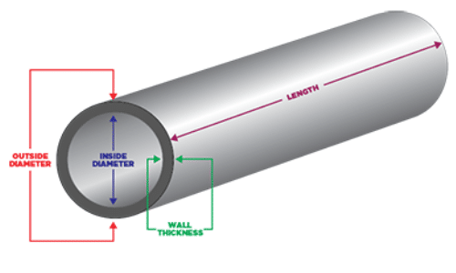
Fig 1.1: Relationship between OD, ID, and Wall Thickness
Material Versatility & Performance
Schedule 40 isn't just a size—it's a performance benchmark. We provide Sch 40 piping in various metallurgical grades to match your specific environmental and pressure requirements.
Carbon Steel Sch 40
- ASTM A53/A106: Ideal for steam, water, and gas lines.
- Cost-Effective: Best balance of strength and investment.
- Coating Ready: Easily galvanized or epoxy coated.
- High Machinability: Excellent for field welding and threading.
Best for: General Construction, Oil & Gas, HVAC.
Stainless Steel Sch 40
- Grade 304/316: Superior resistance to oxidation and acids.
- Hygienic Surface: Smooth internal bore prevents bacterial growth.
- Extreme Temps: Maintains integrity in cryogenic or high-heat zones.
- Zero Maintenance: Eliminates the need for protective coatings.
Best for: Chemical Processing, Food & Pharma, Marine.
*Actual pressure ratings vary by NPS and material grade. Consult our engineering team.
Schedule 40 vs. Schedule 80
Choosing the right thickness is critical for both project safety and budget optimization. While Sch 40 is the "Standard," some high-pressure environments demand the "Extra Strong" performance of Sch 80.
Technical Selection Guide
| Parameter | Schedule 40 (STD) | Schedule 80 (XS) |
|---|---|---|
| Wall Thickness | Standard Weight | Extra Thick (+ Approx. 30%) |
| Internal Diameter | Larger (Higher Flow) | Smaller (Lower Flow) |
| Pressure Rating | Medium to High | Maximum (High Pressure) |
| Project Cost | Economical / Standard | Premium (Higher Material) |
Pro Purchase Tip:
If your application involves standard water, air, or oil transport at ambient temperatures, Schedule 40 provides the most cost-effective solution. Only upgrade to Sch 80 when dealing with high-pressure steam, chemical stress, or structural requirements needing extra rigidity.
Visual Cross-Section
Note: Both schedules share the same Outside Diameter (OD). The difference lies in the internal wall thickness and reduced Inside Diameter (ID).
Still unsure about the thickness for your specific PSI requirements?
Ask an EngineerThe Standard for Industrial Success
From modern infrastructure to high-pressure processing, Schedule 40 pipe is the globally recognized baseline for reliability. Discover how SS Alloy Steel supports every major industry.
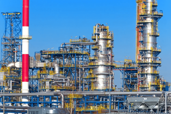
Oil & Gas Transport
Engineered to handle low-to-medium pressure hydrocarbons, our Sch 40 pipes are the go-to choice for upstream and midstream transmission lines where wall thickness consistency is non-negotiable.
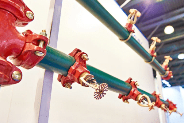
Fire Sprinkler Systems
Schedule 40 black and galvanized pipes provide the necessary structural integrity and internal diameter to meet strict NFPA codes for automated fire suppression systems.
Structural & Framing
Beyond fluid transport, the high strength-to-weight ratio of Sch 40 makes it ideal for scaffolding, handrails, industrial shelving, and modern steel-frame furniture.

Municipal Water Lines
The standard wall thickness provides an optimal balance between cost and longevity for municipal water distribution and large-scale agricultural irrigation projects.

Need a Custom Industrial Solution?
We provide tailored Schedule 40 sourcing for large-scale infrastructure projects worldwide.
Integrated Fabrication Services
Streamline your supply chain. SS Alloy Steel delivers "Ready-to-Assemble" Schedule 40 components, eliminating the need for costly third-party processing.
Precision Threading
High-quality NPT and ISO threading for secure, leak-proof connections. We verify thread profiles with calibrated gauges to ensure seamless field assembly.
Precision Cut-to-Length
Utilizing heavy-duty band saws for accurate定尺切割. We adhere to tight length tolerances (+/- 1mm) to minimize your on-site scrap and rework.
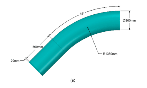
Weld-Prep Beveling
Automated machine beveling to create perfect 30°, 37.5°, or custom angle pipe ends, ensuring superior weld penetration and structural joint integrity.
Protective Coating
Extend pipeline service life with factory-applied treatments including Hot-Dip Galvanizing (HDG), FBE, 3LPE, or standard temporary anti-rust varnish.
Technical Support & FAQ
Expert insights into Schedule 40 piping specifications, procurement, and field applications.